In this article we look at another sensor – this time its a L3G4200D 3-axial digital gyroscope and we will connect it to our Beaglebone and we will have a python example
First lets take a look at the sensor in question
The L3G4200D is an is three-axis angular rate sensor, with a digital I2C/SPI serial interface standard output.The device has a full scale of ±250/±500/ ±2000 dps and is capable of measuring rates with a user-selectable bandwidth. The device may be configured to generate interrupt signals by an independent wake-up event. Thresholds and timing of the interrupt generator are programmable by the end user on the fly.
The L3G4200D has an integrated 32-level first in first out (FIFO) buffer allowing the user to store data for host processor intervention reduction
Specifications:
Chip: L3G4200D
Power Supply: 3-5V
Communication Mode: IIC / SPI communications protocol
Measuring Range: 250/500/2000 dps
Communication Interface: I2C (up to 400 kHz) or SPI (10 MHz; 4 & 3 wire)
Operating temperature: -40 to +185 °F (-40 to +85 °C)
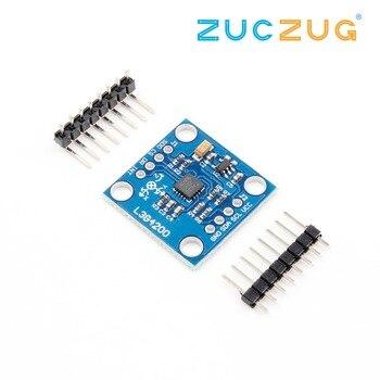
This was the version of the sensor I bought
Parts Required
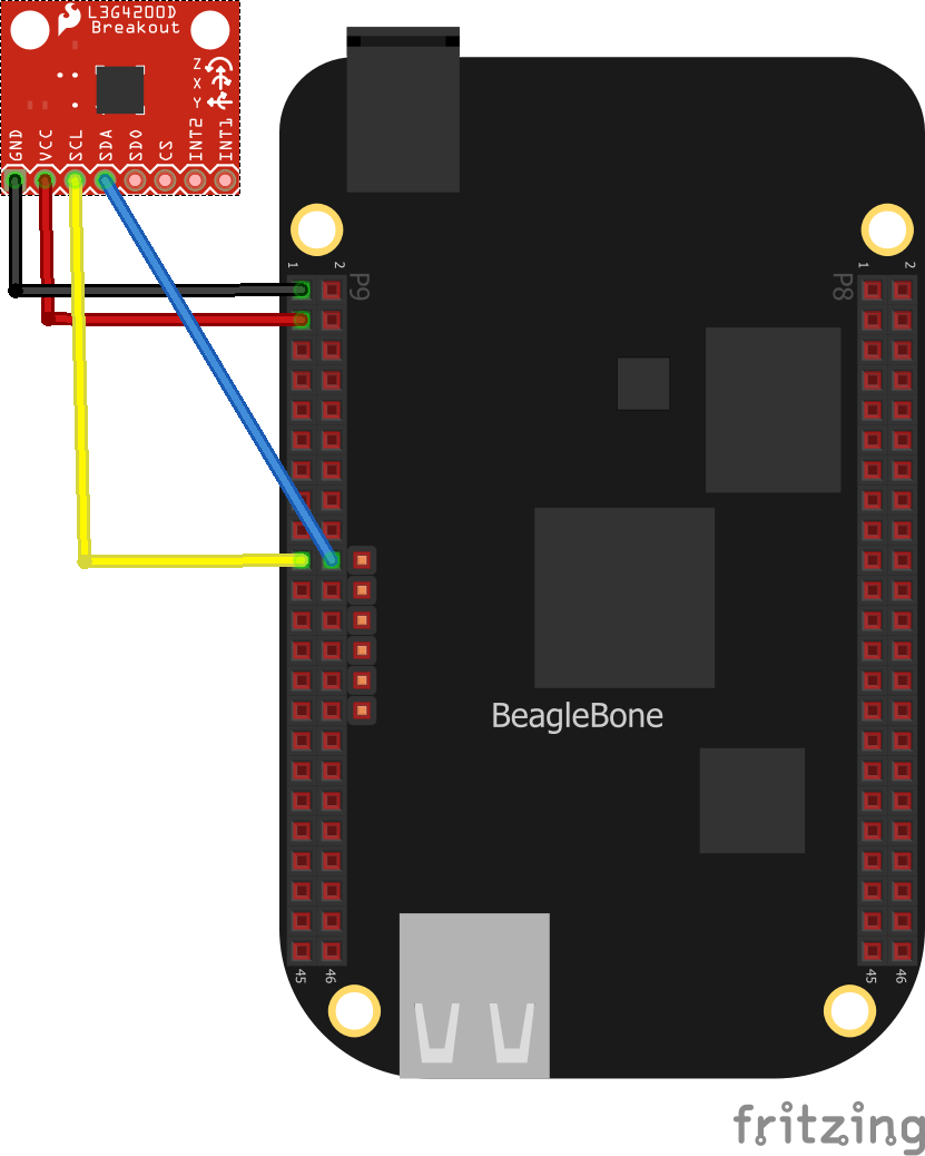
Schematic/Connection
| Beaglebone | Module |
| 3.3v – P9.3 | Vcc |
| Gnd – P9.1 | Gnd |
| SDA – P9.20 | SDA |
| SCL – P9.19 | SCL |

Code Example
This was a controleverything example that I modified as my sensor had a different I2C address. If your sensor does not work change the address from 0x69 to 0x68
You can always check the I2C address from the terminal first by typing in
i2cdetect -y -r 2
[codesyntax lang=”python”]
import smbus
import time

# Get I2C bus
bus = smbus.SMBus(2)

# L3G4200D address, 0x69(104)
# Select Control register1, 0x20(32)
#		0x0F(15)	Normal mode, X, Y, Z-Axis enabled
bus.write_byte_data(0x69, 0x20, 0x0F)
# L3G4200D address, 0x69(104)
# Select Control register4, 0x23(35)
#		0x30(48)	Continous update, Data LSB at lower address
#					FSR 2000dps, Self test disabled, 4-wire interface
bus.write_byte_data(0x69, 0x23, 0x30)

time.sleep(0.5)

# L3G4200D address, 0x69(104)
# Read data back from 0x28(40), 2 bytes, X-Axis LSB first
data0 = bus.read_byte_data(0x69, 0x28)
data1 = bus.read_byte_data(0x69, 0x29)

# Convert the data
xGyro = data1 * 256 + data0
if xGyro > 32767 :
	xGyro -= 65536

# L3G4200D address, 0x69(104)
# Read data back from 0x2A(42), 2 bytes, Y-Axis LSB first
data0 = bus.read_byte_data(0x69, 0x2A)
data1 = bus.read_byte_data(0x69, 0x2B)

# Convert the data
yGyro = data1 * 256 + data0
if yGyro > 32767 :
	yGyro -= 65536

# L3G4200D address, 0x69(104)
# Read data back from 0x2C(44), 2 bytes, Z-Axis LSB first
data0 = bus.read_byte_data(0x69, 0x2C)
data1 = bus.read_byte_data(0x69, 0x2D)

# Convert the data
zGyro = data1 * 256 + data0
if zGyro > 32767 :
	zGyro -= 65536

# Output data to screen
print "Rotation in X-Axis : %d" %xGyro
print "Rotation in Y-Axis : %d" %yGyro
print "Rotation in Z-Axis : %d" %zGyro
[/codesyntax]
Output
Run this example and you should see the following.
debian@beaglebone:/var/lib/cloud9/$ python L3G4200D.py
Rotation in X-Axis : 80
Rotation in Y-Axis : -8
Rotation in Z-Axis : 24
debian@beaglebone:/var/lib/cloud9/$ python L3G4200D.py
Rotation in X-Axis : 68
Rotation in Y-Axis : 9
Rotation in Z-Axis : 64
debian@beaglebone:/var/lib/cloud9/$ python L3G4200D.py
Rotation in X-Axis : 138
Rotation in Y-Axis : -42
Rotation in Z-Axis : 16
Links

