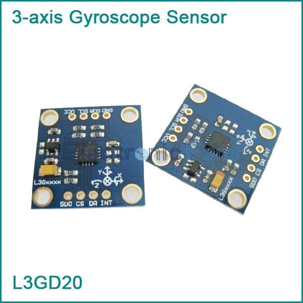
The L3GD20 is a low-power three-axis angular rate sensor. This is the module I bought for reference
More information can be found at http://www.st.com/content/st_com/en/products/mems-and-sensors/gyroscopes/l3gd20.html about the sensor

Features
- Three selectable full scales (250/500/2000 dps)
- I2 C/SPI digital output interface
- 16 bit-rate value data output
- 8-bit temperature data output
- Two digital output lines (interrupt and data ready)
- Integrated low- and high-pass filters with user-selectable bandwidth
- Wide supply voltage: 2.4 V to 3.6 V
- Low voltage-compatible IOs (1.8 V)
- Embedded power-down and sleep mode
- Embedded temperature sensor
- Embedded FIFO
- High shock survivability
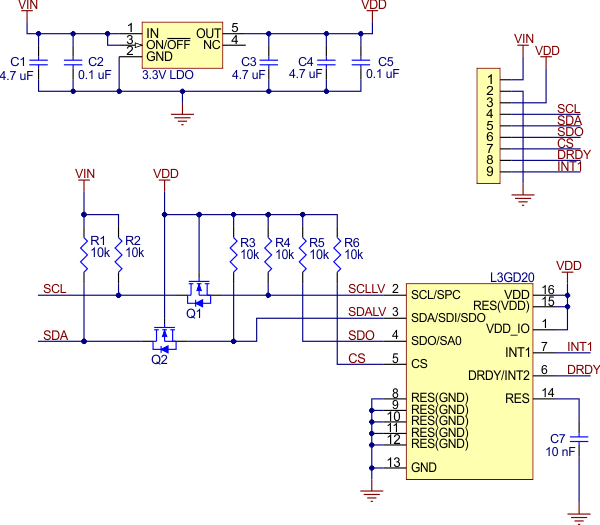
Here is a schematic showing the module I bought

Connection and Layout
| Linkit One Connection | GY-50 L3GD20 connection |
| 3v3 | Vcc |
| Gnd | Gnd |
| SDA | SDA |
| SCL | SCL |
here is a layout showing these connections

Code
I managed to find the following library that seemed to work well – https://github.com/pololu/l3g-arduino
This is the test example
[codesyntax lang=”cpp”]
#include <Wire.h>
#include <L3G.h>

L3G gyro;

void setup() {
  Serial.begin(9600);
  Wire.begin();

  if (!gyro.init())
  {
    Serial.println("Failed to autodetect gyro type!");
    while (1);
  }

  gyro.enableDefault();
}

void loop() {
  gyro.read();

  Serial.print("G ");
  Serial.print("X: ");
  Serial.print((int)gyro.g.x);
  Serial.print(" Y: ");
  Serial.print((int)gyro.g.y);
  Serial.print(" Z: ");
  Serial.println((int)gyro.g.z);

  delay(100);
}
[/codesyntax]
testing
Open the serial monitor and you should see something like this
G X: -2 Y: -183 Z: 86
G X: 186 Y: -169 Z: -125
G X: 167 Y: -98 Z: 24
G X: 179 Y: -107 Z: 23
G X: 215 Y: -101 Z: 46
G X: 211 Y: -147 Z: 3
G X: 213 Y: -94 Z: -9
G X: 224 Y: -66 Z: 35
G X: 181 Y: -74 Z: 5
G X: 198 Y: -50 Z: 29
G X: 233 Y: -114 Z: 21
Links
You can pick up one these sensors for about $4
L3GD20 3-axis Gyroscope Sensor replace L3G4200D Angular velocity module
